>Scara_Printer
Last Edit: Feb. 13, 2011, 10:03 p.m.
SCARA robot printer
I've wanted a 3d printer for a long time. I finally decided to get one, but I wanted to make it from scratch. Most of the current homebrew 3d printers are cartesian, where they move in the x,y plane with perpendicular axis (and for good reason, as you'll see in a bit). I decided to do something a little different. I went with a SCARA style arm.
First of all, here she is.
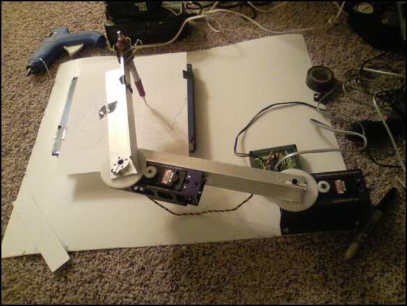
It's two HS-785HB servos with 4:1 gear boxes, some 1.5" angle aluminum I got from home depot and cut to length, and a serial controller. I'll talk more about the servo choice later.
I don't have an extruder yet, so I just hot glued an ink pen onto the end of the arm since I was so excited to test it out.
So the first thing I needed to do was figure out how to translate an x,y coordinate into a theta1, theta2 pair. This is... get ready for it... DUN DUN DUN... inverse kinematics (and forward kinematics is taking the two angles and returning an x,y pair.) A quick google didn't turn up any python inverse kinematics libraries, so I found some discussion on it and threw together a simple solver. Luckily it turns out to just be a little bit of trig, so it wasn't a big deal.
Now that I have the angles I need, I have to figure out how to tell the servos to go to those positions. When I ordered the servos, I got an 8-port servo controller that communicates over serial. It takes a number between 0 and 254 (255 is reserved for the control bit, so can't use that) and sends the correct pulse width signal to get the servo in the right position. More on that limitation later. The resulting control software can be seen here.
To test out the system, I decided I'd tell it to draw a square and see how it looked. This was the result:
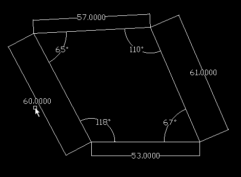
Clearly, it needs some tuning. I thought about it for a while, and decided that the length of the sides was probably mostly dependent on having the correct arm length, so I set about tweaking the arm lengths until the sides were the right length. That solved the size problem, but I was left with a parallelogram. I tried a few things to fix this and almost gave up when it came to me: the angle is offset. I added an offset to the elbow axis and voila, a passable square.
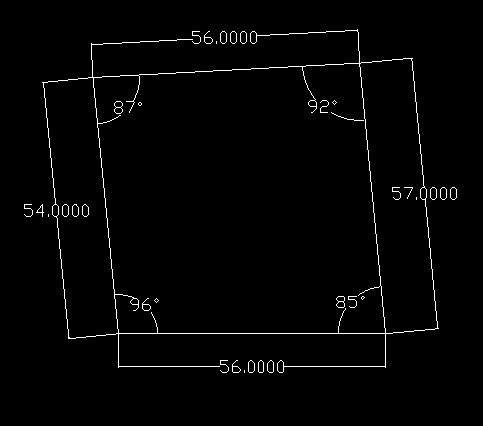
It's not perfect, but I decided it would do. It wasn't the right size, but I kept the same arm ratio and changed the arm sizes until it was correct.
Now that it was dialed in, I decided to have it draw something and see how it looked.
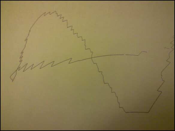
Here's the sine wave it drew. The line running across the middle is the x-axis. Clearly quite jagged. Here's where the discussion of servo and controller choice comes in. The servos I got rotate 3.5 turns, and with the 4:1 ratio, that gives 315 degrees of rotation. The controller has a resolution of 255, so this gives a minimum angle change of 1.2 degrees. That might not sound like much, but here's what wolfram alpha says about it:
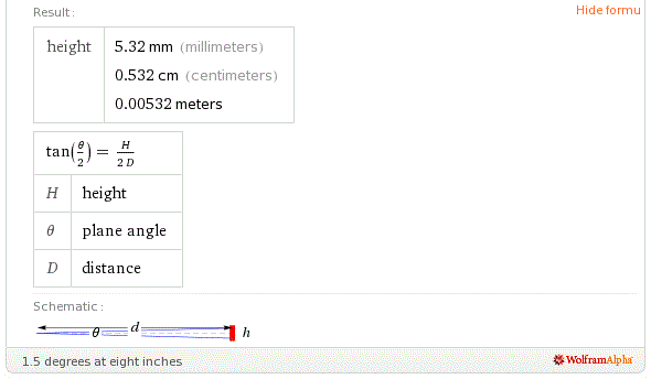
So you can see that at eight inches, 1.5 degrees gives a travel distance of 5mm, or roughly a quarter inch. So what I need to do is get a servo with a smaller travel distance. It will reduce the draw area, but I don't ever see a need to draw in a huge 300 degree range. If anything 180 degrees at the elbow, and 45 at the shoulder should be sufficient.
Also, to reduce the jitter, I would like to get an arduino and control the servos that way. The controller I have doesn't like to always move both servos at once and you can't control the speed from it.
The servos I got were also expensive for hobby servos at $40 vs around $15 for lower end ones. The gearboxes were $50 each, and you could build your own, but I do like these, they have dual bearings and zero play so that really helps support the weight of the arm. The whole thing cost about $260, so it's considerably cheaper than a cartesian like reprap (though not nearly as accurate, and I still need an extruder which is $150 over at makerbot, but that's still less than half the price.)
Last, but not least, here is a crappy crappy crappy youtube video I've got of it running.
 DanoMagnum.com